Fabricating
Hull Components
(Goodby, to Trial & Error Methods)
'Metal Fabrication' is the creation of metal structures by cutting and bending sheet-metal, than assembling those formed components into a pre-determined product.
‘Applied Metal Boatbuilding Methods’ – ‘Sheetmetal Pattern Development’ picks up after the hull and deck of a boat is constructed. Devoid of all features or a 'Bare Hull'. It begins another phase of the build with the fabrication of integrals such as but not limited to: Coamings, Hatches, Window Ports, Companionways, and Tanks. Some builder may ever want to fabricate there own mast and booms.
Fabrication of these components by the builder is another major economic advantage of building in steel or aluminum. Components such as these can be fabricated for nickels and dimes on the dollar over purchased manufactured versions of the product.
Custom fabricated steel components are also more in keeping with the hulls construction material ensuing a harmonious steel design that is not attainable using components designed for another construction material.
Layout and fabrication of these type of components are determined by well established empirical formulas known as ‘Bend Allowance’ and ‘Bend Deduction’. These formulas are in universal use throughout the metal fabrication industry.
‘Applied Metal Boatbuilding Methods’ – ‘Sheetmetal Pattern Development’ is a Metal Fabricators course in ‘Precision Sheet Metal Layout’. Teaching the theory, principles and application of these well established Sheetmetal layout formulas to calculate the cut sizes, locations of bend lines and interior features demonstrated through the fabrication of marine components typical to steel and aluminum pleasure craft.
It is a complete guide to all persons in the metal fabrication industry be they Precision Metal Fabricators or ‘One Of’ Metal Boat Builders. ‘Applied Metal Boatbuilding Methods’ – ‘Sheetmetal Pattern Development’ is basic to rounding out your metalworking layout skills.

Architectural drawings routinely represent only the size and location for features such as hatches and their coaming by way of a single drawn line as shown in the ‘Construction Plan and Profile' for the Bezier 35 n below.

The first thought should be how you will approach to the actual fabrication. For example, our Thru-Deck Coaming will be fabricated in two sections from sheet material and formed in a 'Press Brake'. After which the two fabricated sections will be welded together before installation in the deck structure.
With the fabrication and installation methods straight in you mind your mind gather all the dimensional information provided in the architectural drawings and or specifications.
- I scaled the outside dimension of the coaming off the 'Construction Plan and Profile' drawing at 16.375" in both directions.
- I found the thickness of the coaming in the Specification at 0.187" thick.
- Since the deck is curved I made a cardboard template an determined that the coaming at the centerline of the deck would be 4.186" in height while the height at the ends would be 4.344".
- I also decided that the corners of the coaming would have an 'Inside Radius' of0.937". (This radius is somewhat arbitrary, usually determined by the availability of 'Press Brake' tooling.)
The Layout Process
To begin the layout process for any component and in this case a Fore-Deck Hatch Coaming, I usually start out with a rough 'Hand Sketch'.
Below is my hand sketch showing all the principle 'Apex' dimensions (Dimensions outside to outside), Inside Radius dimension, Weld seam location, and material thickness in a Plan View.
For now, knowing the term 'Apex' dimensions sufficient. For further details see my book - 'Applied Metal Boatbuilding Methods'.
(Available on Amazon)
Draw a Plan View of the coaming:


Draw a Profile View of the coaming:

Your drawing should indicate crown in the coaming, from your template, which follows the curve of the deck transversely. The coaming widest point is 4.344” at the centerline to 4.146” at the ends.
From these drawings all the dimensional information necessary to layout a flat pattern for the coaming can be entered into the development spreadsheet, which is free to download from the below link.

Layout Method
To calculate the 'Cut Size' two (2) sheet-metal formula's, used every day in the metal fabrication industry, will be used - 'Bend Allowance' and or 'Bend Deduction', while these calculations to determine the 'Cut-size' for the example coaming is simple math, they are somewhat complex and are fully described in the book. To offset this the following screenshot shows 'OD Apex' Excel spread sheet.
This Excel spread sheet calculates the 'Cut Size' from the dimensional information of your initial sketches.
You can download this Excel file and all the other spreadsheets used in 'Applied Metal Boat Building Methods' by Clicking on the below link.

The Inputs:
- The first column is where you enter the Apex Dimensions. (In this case the Apex Dimensions are the same as the Outside Dimensions - 8.187" x 13.375" x 8.187".) See my book 'Applied Metal Boat Building Methods' for more details.
- The next column is where you would specify the 'Bend Angle' for each bend. Here it is 90-degrees for both bends.
- In the next column is where you would specify the 'Inside Radius' for each bend- 0.937" for both.
- The next column enter the 'Material Thickness'.
The Outputs:
For now we are only interested in the last three Outputs.
- Cut Size - Is the calculated length or width for the component.
- Bend Lines from 0 - The distance from the starting edge of the flat layout to each Bend Line.
- Between Bend Lines - The distance between each bend Lines.
The Hand Drawing:
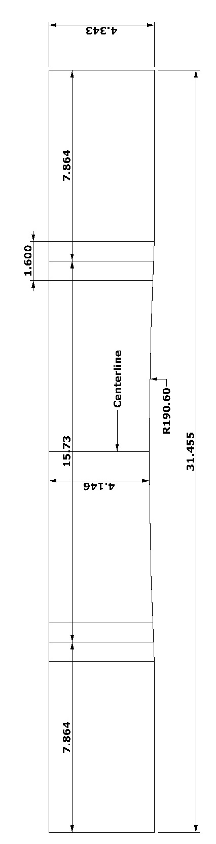
The hand drawing below represents the flat patternfor half of the Fore Deck hatch coaming.
- The overall cut-size is 31.455" x 4.343". This cut-size is for one half of the coaming. Two Pieces are required. They will be welded together to complete the finish coaming.
- There is a 90-degree bend 7.864" in from each end of the 31.455' dimension.
- a 1.875" diameter top punch will be use to form the radius corners for this coaming layout.
- Notice that the radius of the deck is cut between the two bend lines.

While your hand sketch for the flat layout is adequate for your intended purposes , I am including the below drawing which put the layout in prospective.
All Copyrights Reserved - MetalSailboats.com
2009 - 2025
|
|
|
|
 |
|
|
|
|
|
|
|
|