Katspaw Dinghy
The Katspaw Dinghy is an aluminum redesign of the classic Plank-on-Frame Catspaw Dinghy designed somewhere back in the early 1900's.
I redesigned this classic Rowing - Sailing Dinghy to introduce 'One of' metal boat Builder's to the concept of building a True Round aluminum hull by way of 'Approximate Development' that would not break the Bank by way of a Build that has added value do to its classic appeal.
Building this classic design will hone your metal-working skills before the possibility of taking on a larger 'Approximate Developed' true round hull design.
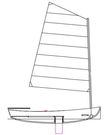
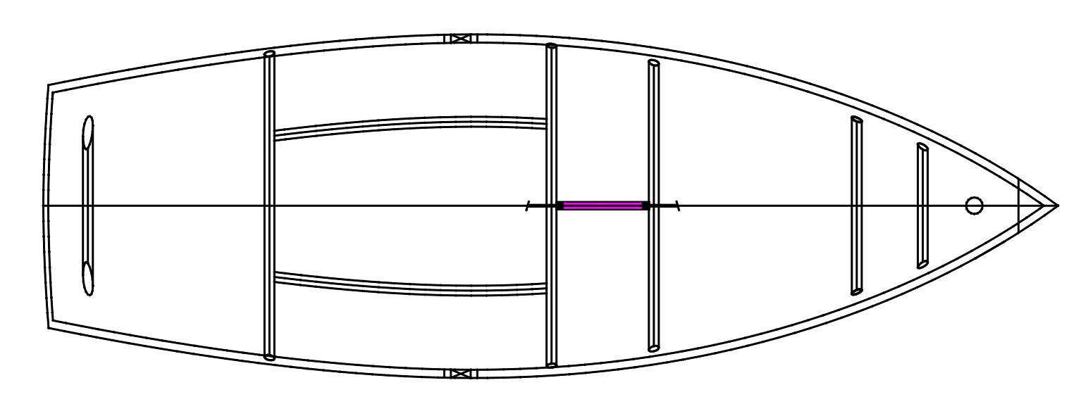
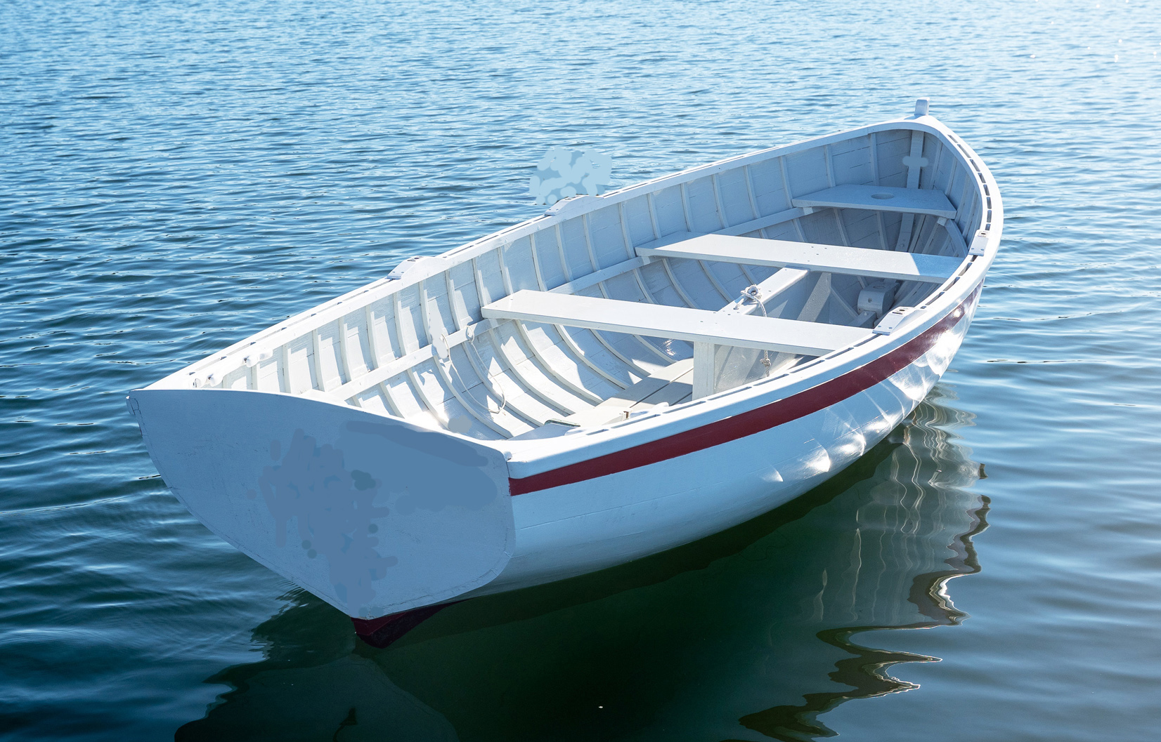
The following picture shows the Plank on Frame designed by Herreshoff somewhere in the early nineteenth century.
Lines Drawing
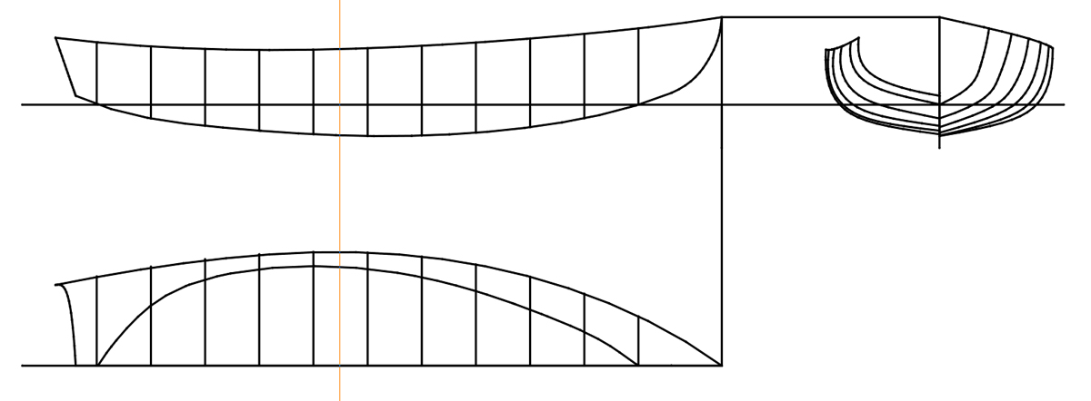
- Length Overall - 153.750"
- Design Waterline Length - 125.250"
- Freeboard Forward - 20.125"
- Freeboard Aft - 15.500"
- Beam on Deck - 52.250"
- Beam at Waterline - 4.125"
- ---------------------------------------------
- Design Weight of Hull - 537.000#
- Calculated Weight of Hull - 302.500#
- Crew Weight - 200#
- Heavy Load Weight - 502.50
- -------------------------------------------
- Longintudinal Center of buoyancy - 85.210"
- Longintudinal Center of Gravity - 85.115"
- Vertical Center of buoyancy - 2.270" Below DWL
- Vertical Center of Gravity - 4.977" Above DWL
Floation
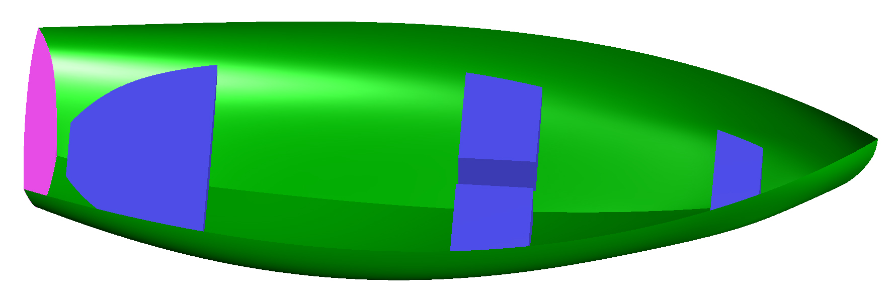
Being constructed of aluminum the boat has no possibility of floating in a swamped condition, therefore the 'Katspaw Dinghy' incorporates flotation chambers neatly placed under the Fore deck, Helm seating, and aft deck.
According to my calculations the minimum floatation required, in cubic feet, to support a swamped Catspaw Dinghy and 400 pounds of crew (Four Hundred pounds more than the weight of the weight of the boat itself) is 4.643 cubic feet.
The floatation designed into the hull under the Fore deck seat is 0.649 cubic feet, under the Center is 3.5230 cubic feet, and under the Aft seat 1.234 cubic feet.
Notably there is 0.763 cubic feet of reserve flotation. The image below shows these void spaces.
Framing System
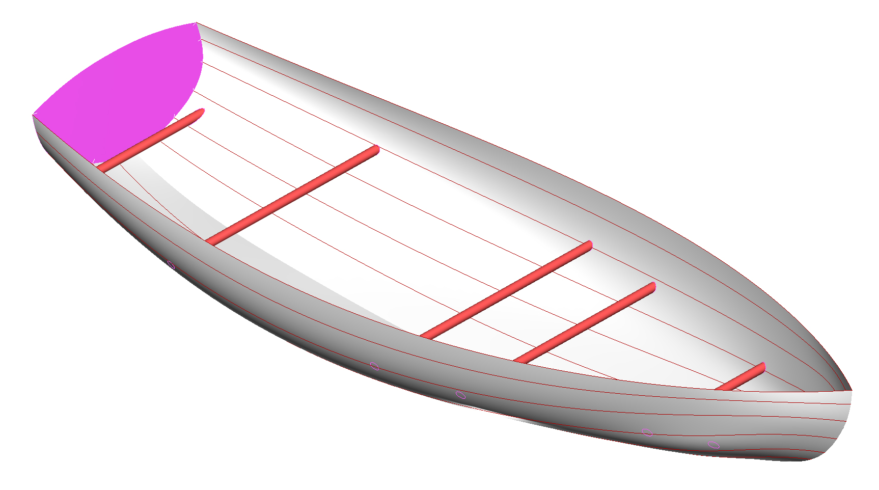
The aluminum Katspaw Dinghy has no Transverse frames only Longintudinal frames of which there are five, Red, between the sheer longitudinal and Center Vertical Keel - CVK.
Transverse framing support is provided by six (6) round tubes across the beam of the hull. These tubes penetrate the shell plating plating and are supported by Doubles Plates welded to the inside surface of the shell plating.
These Transverse Framing Tubes are a vital part of the flotation system as previously described as they support the void flotation compartments.
Transverse Formers
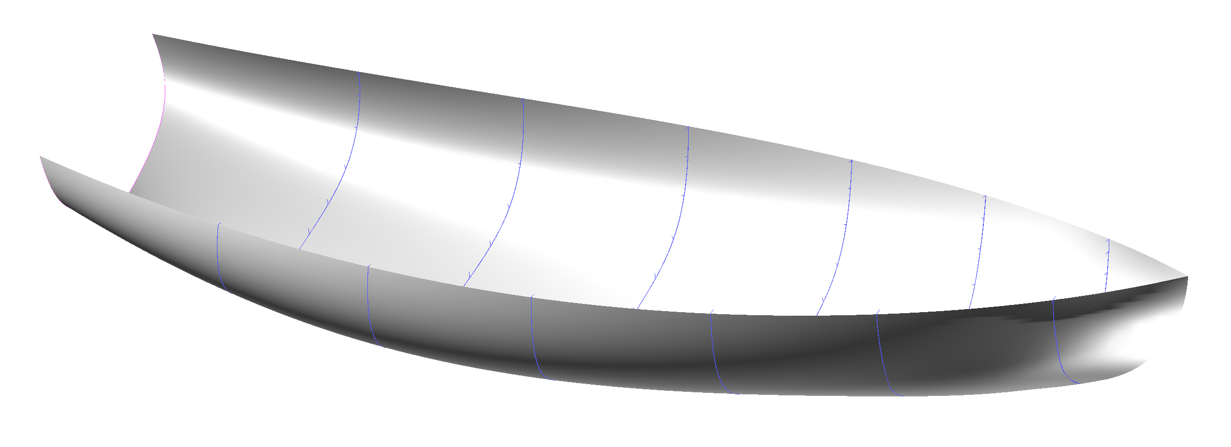
The Transverse Formers have no structural value. They Their profiles are cut from suitable dimensional stable sheet material. Their only purposes is to locate the Longintudinal frames, which in turn locate the position of the Shell plating. They will be removed after the Shell Plating has be tack weld to the Longintudinal Frames.

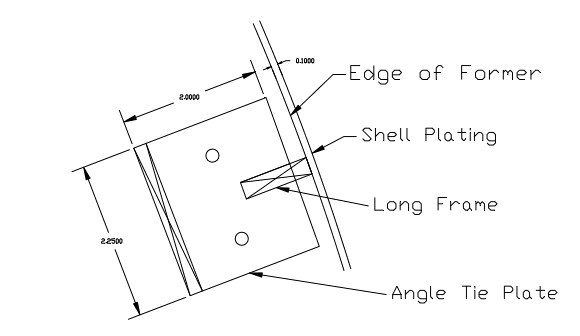
It should be obvious that the aluminum longintudinal frames cannot be tack weld to the profiled transverse former. Therefore aluminum angle clips are fabricated as an interface.
- These angle clips are fabricated from 0.187" thick aluminum
- Note the 0.250" wide slot at a depth of 0.750".
- The depth of the slot will be located at the depth of the slot in the Former.
- The Angled clip is to be thru-bolted to the Former.
- The 0.750" leg of the angle serves as a clamping point to pull the Longintudinal frame to the proper depth.
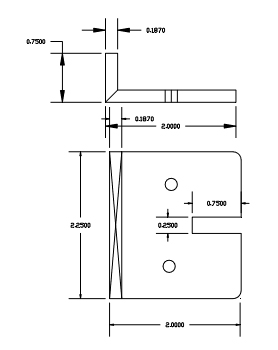
The following drawing shows the Angled clip in location at one of the longintudinal frame notches in a Former.
Looking at the below drawing, remembering that the clip is 0.187" thick, it is possible to tack weld the Longintudinal frame to the clip on the opposite side of the angled clip. Since the angle clip is 0.187" thick, there is plenty of thickness for a tack weld. Remember that these clips will be removed after the Shell Plating has bee tack welded into place.
StrongBack
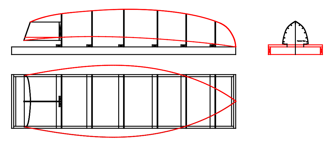
The Strongback shown below in plan. profile, and section views is constructed from 3.500" x 1.500 and 5.500" x1.500" common lumber. Other materials can be used if you like as long as you keep the distance's between Formers as shown.
Remember that the accuracy of the Build all starts here! Everything that follows depends on the accuracy of the Strongback.
Shell Plating:
Full-size Shell Plate paper patterns are provided to the Builder in Pdf file format and can be print at most office supply stores.
Scaled architectural drawing will be printed to the scale given on the drawing by default. After printing, store at room temperature and keep dry. Do not store in a damp environment. Always take care to prevent folds and creases.
Paper Patterns contain essential fabrication information that cannot be conveyed by Cnc cutting files. The following drawing is an example of a full-size paper plot, located at one of the transverse hull Formers.
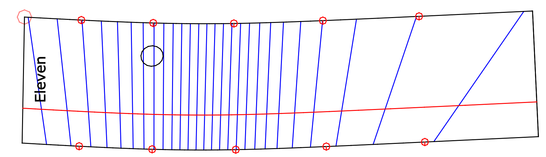
- The above shell plate is the 11th shell plate from the bow.
- The outside perimeter of the shell plate is defined by black lines.
- Notice the Red points on the perimeter of the the shell plate. These points define the crossings of the Longintudinal frames.
- The curved horizonal line, near the center of the shell plate pattern indicates the that this shell plates aligns with a Transverse former.
- The elliptical circle indicates where a transverse tube penetrates the hull shell surface, which supports a Void chamber.
- The askew unequally space blue line are three-degree bend lines that form the curvature of the shell plate.
All Copyrights Reserved - Metalsailboats.com
2009 - 2026
|
|
|
|
 |
 |
|
|
|
|
|
|
|
|