The English Wheel
Mathematical Algorithms can flatten a computer generated three dimensional 'True Round' surface onto a single plane, defining both the perimeter of the blank and 'Strain' counters which will direct the roller of an 'English Wheel' to form the sheet-metal, from which the hull will be built, back to its three dimensional shape.
In this example, the 'True Round' center surface (green) of the 'Bezier 28' will be flattened onto a single plane, then the process of forming this flat sheet-metal layout back to its intended three dimensions will be discussed.


What is unique about the 'Bezier 28' is that it is designed with a combination of surfaces types. The upper and lower surfaces (magenta) are 'Elementary' or 'Developable' surfaces.
This type of surface is used in 'Hard Chine' designs. In the 'Bezier 28' they are used for ease of construction, while providing the look and feel of a 'True Round' design by placing a 'True Round' surface (green) between 'Developable' surfaces.
While the Authors method of 'Approximate Development' is an option to form the 'True Round' shell plating, some 'Buildes' wants to form the 'True Round' shell plating, between the Developable surfaces of the 'Bezier 28', using the Traditional method of 'English Wheeling' to form the hulls shell plating.
To that end Computational software using Mathematical Algorithms were used to reduce the three dimensional computer generated "True Round' surface (green) of the 'Bezier 28' onto a single plane.
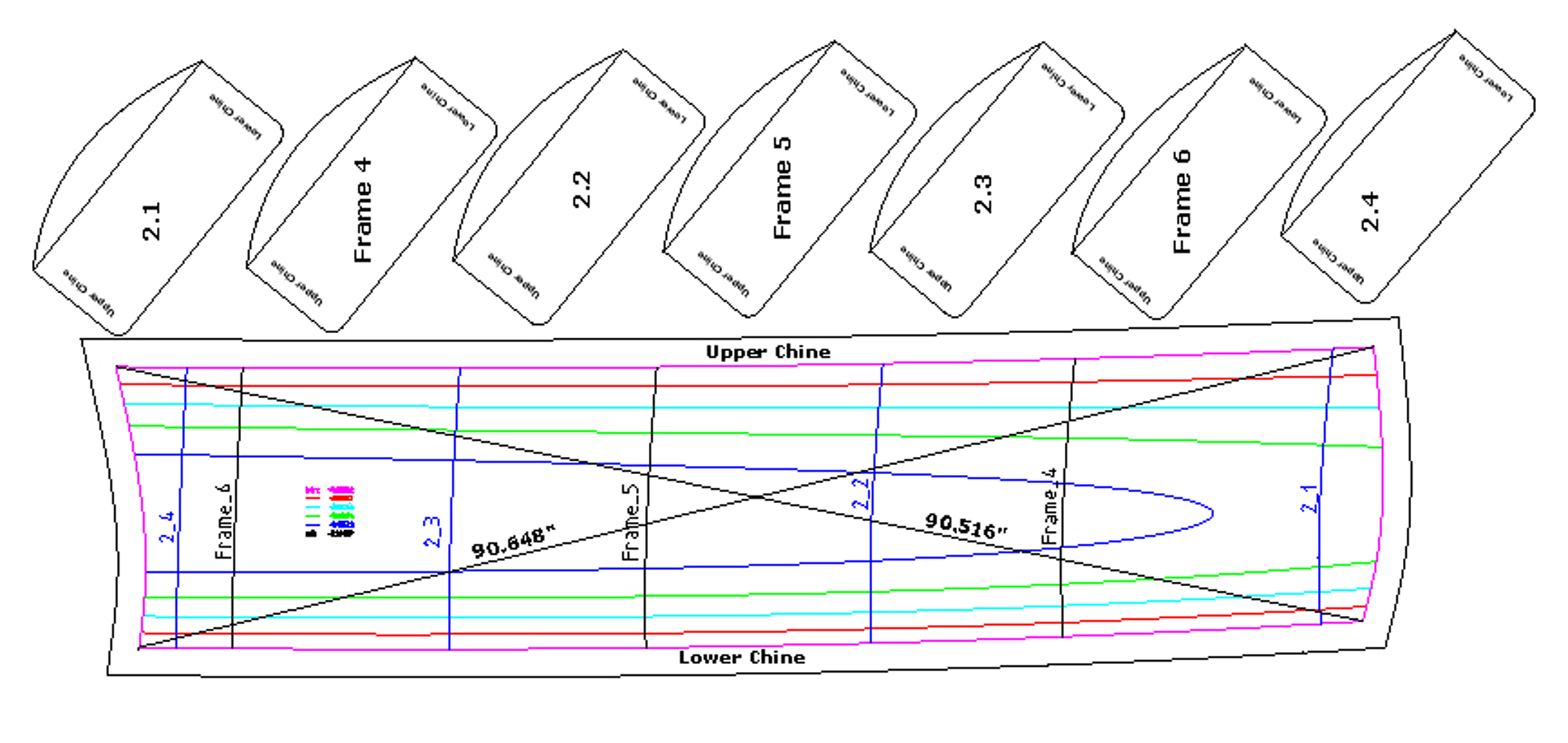
The image below represents the entire length of the flattened 'True Round' surface.

It however, would be impracticable from a construction standpoint to form the entire surface length of the 'Bezier 28' in one piece. Common practice to divide the surface into workable segments. Therefore, the above pattern is divided into four sub-patterns. Each segment is just under eight feet in overall length, a standard sheet length for sheet material.

 |
About the Patterns
Strain Counter Lines:
- The magenta colored line is a Counter line representing the perimeter of this surface segment. After forming the blank will fit perfectly to the hulls framework and edges of the Developable surfaces. No Trimming necessary!
- The contour map of 'Strain' distribution is shown in four colors, Red, Cyan, Green, and Blue lines. Each color represents a different value of 'Strain.
- The 'Strain' value is a 'Percent' (%) of how much the material is expanded by the forming process. For example, if the 'Strain' is given at -0.003 means that the material will be 0.003% thinner in that area of the surface.
- The 'Strain' values for the sample part are: The boundary line, Magenta, is given as 0.000, the red line is given as -0.00132, the Cyan line is given as -0.00264, the green line is given as -0.00396, and the blue line as -0.00528.
Transverse Lines:
- The pattern includes the locations of Frames: Four, Five, and Six. These curved line will become straight when the pattern has been formed back to its original Three Dimensional shape. When positioning the formed shell plate onto the framework there will be an exact alignment.
- To the right of the Flat layout you will find 'Forming' templates. These template are the shape of the of the transverse frames. They are used to guide the forming process. Here they are shown as convex, curving outward, fitting the inside of the hull surface. However they can be concave, not shown, fitting the outside of the surface.
- Transverse lines 2.1, 2.2, 2.3, and 2.4 are addition forming template locations to guide the forming process, between the transverse frame and the ends of the template.
Other Lines:
- The black line around the pattern is offset 2" from the boundary line of the pattern, magenta. (See English Wheeling Tips)
- The black 'Cross Lines' give the finial cross-dimensional check of the quality of the Wheeling process.
Note:
- Mathematical Algorithms have taken a sizable chunk of the skill required to form 'True Round' shell plating using the 'English Wheel'. There however is still a Chunk of Skill required.
English Wheeling Tips
- 'English Wheeling' is an incremental process. Always start with the slightest amount of pressure against the metal, just enough so the metal will not skip or slip through the wheels. Too much pressure will produce roller marks and mar the metal. The first few passes of the shell panel through the wheel will show if the pressure setting is correct. There should be some shaping, but definitely no marring.
- It takes several different wheeling anvils to achieve a high-crowned curve in a shell panel. Start with a low-crowned anvil and work up to more distinctly curved anvils as the shape progresses. Starting with an anvil with too much crown will mar the metal.
- Move the shell panel through the wheel in a gentle and smooth manner as you guide the panel laterally through the wheel to form the curve.
- How the shell panel is moved through the wheel is very important! Each pass of the shell plating through the wheel must be close enough to the previous one so they will overlap slightly.
- The actual motion of moving the shell plating back-and-forth through the 'English Wheel' is called tracking. However, the shell panel must also be moved from right-to-left, or from left-to-right as well, without missing any section of shell plating. Each track must be parallel to the previous one. Do not zigzag across the shell plate. This will cause waves instead of smooth curves.
- If more shape is required on one side of the shell plating than the other, do more than one wheeling. Start by wheeling short passes on the area you want to be curved more, then go over the whole part and overlap the first wheeling.
- When English Wheeling, never run the wheel past the edge of the pattern, especially along its longitudinal length of the shell plate. To this end all patterns will incorporate a two inch border.
- Along the short side, when the pattern has been divided into segments for construction purposes, as discussed previously, joining section need not have margins. The pattern segments that end the shell plating at the bow and stern of the hull will have a two inch border, the wheels here again are not to be run off the material.
- Use the 'Forming' templates often to guide your progress.
- Watch the following video!
The English Wheel in Use
The below link takes you to a 'YouTube' video post detailing the use of the 'English Wheel' to form the 'True Round' aluminum shell plating for the 'Orion 49'. Highlight the below link, then click.
https://www.youtube.com/watch?v=cKymVzeJGeQ
- If only you had this machine.
- Below are two images of the Industrial English Wheel used to form the shell plating for an Aluminum Sailboat.


The following images shows the progress of forming a plate using the forming templates at their given locations.
- Note, the margin of extra material is added the profile of the part along the long side of the part.
- Note, that the templates do not extend to the edge of the sheet. The curved template only extends to the edges of the part itself.


In the image below, I count five, maybe six forming templates. I believe there should be a forming template at each Transverse frame, between each Transverse frame, and one at each end of the pattern.

Heavy duty English Wheel Plans
(Courtesy of 'Graham Radford Yacht Design')
- If you need to form .125" steel and or .187" aluminum plate, you will need an English Wheel, as shown below.
- The wheel needs to powered with a reduction gear that will yield a rotation of about 18 turns per minute at the rollers.
- Hobbyist 'English Wheels' as seen on the Internet are not powered. At best they have a maximum capacity of 14ga steel. You are going to need an Industrial Machine!
- Either search for an industrial wheel or build your own. Shown below is the basic frame structure drawing for an 'English Wheel' use and built by a Profession metal b


All Copyrights Reserved - MetalSailboats.com
2009 - 2025
|
|
|
|
 |
 |
|
|
|
|
|
|