Wave Making Resistance:
When a displacement sailboat begins to move thru the water, water being incompressible, must be moved aside to accommodate the passage of the hull. At low speeds the distance between the crests, along the length of the waterline are short and numerous as shown below.
As speed increases the distance between wave crests becomes longer and fewer along the waterline length as shown below.
Continued increases in speed increase the wave length until the second crest of the bow wave coincides with the crest of the stern wave.
When this convergence take place, the length of the wave matches the length of the waterline. The hull is now suspended between the bow and stern wave crests.
This bow/stern wave coincidence determines the upper speed limit of a displacement hull and occurs at a ‘Speed to Length Ratio’ of 1.34.
Any attempts to increase speed is futile. Increased horsepower will only cause the hulls to sink lower into the stern wave therefore raising the height of the bow wave that the hull is attempting to climb over!
The deeper of the hollow between the bow and stern wave the heavier the boat therefore more resistance to forward motion. This resistance is known as ‘Wave Making Resistance’.
Knowing that a ‘Speed to Length Ratio’ of 1.34 marks the coincidence of the bow and stern waves, we can calculate the potential ‘Hull Speed’ for any given waterline length for a Displacement hull.
1.34 x Square Root of (Waterline Length in Feet)
= Hull speed in Knots
Therefore, it is possible for a heavy displacement
Fractional Resistance:
The other major form of resistance to the forward movement of a displacement boat hull is ‘Fractional Resistance’. The more hull surface in contact with the water the more resistance to forward motion.
The below generic chart shows the relationship between the ‘Speed to Length Ratio’ and Resistance.
The vertical Resistance graph is blank because the curves that represent the fractional, Wave Making, and total resistance are typical no matter the displacement of the hull.
Displacement to Length Ratio:
The ‘Displacement to Length Ratio’ (DLR) is used to compare the relative mass of displacement boats no matter what their length.
A DLR less than 200 is indicative of a racing sailboat. Here the depth of the hollow between the bow and stern wave would be shallow, whereas the depth of the hollow of a hull with a DLR greater than 300 would be deeper.
In other words, the higher DLR more water has to moved out of the way as the hull moves forward. Moving more water requires more energy from either the Sailplan or Engine.
The following ‘Displacement to Length’ chart indicates the type of sailboat design that would result according to it weight alone.
Ultra-Light Under 90
Light 90 to 180
Moderate 180 to 270
Heavy 270 to 360
Ultra-Heavy Over 360
If we couple the 'Speed to Length' ratio with the 'Displacement to Length' ratio
Were 'The rubber meets the road'.
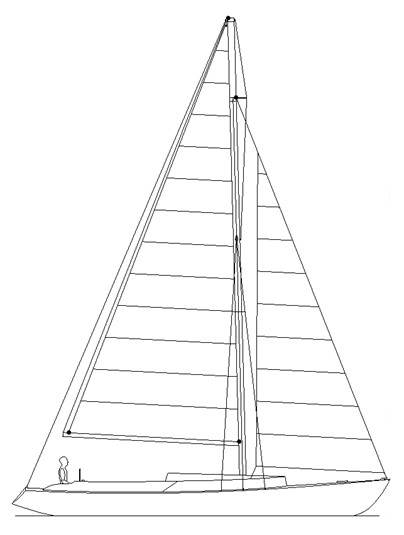
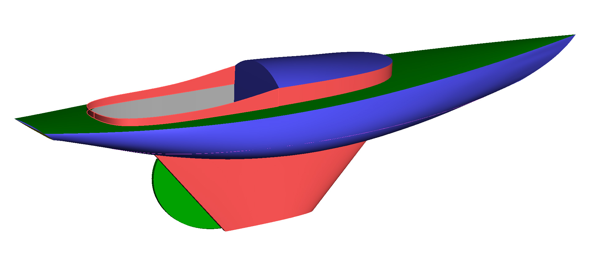
To illustration the relationship between the 'Speed to Length' and 'Displacement to Length' ratios I designed 'Lighting Strike’ a classic style sleek styled thirty-five (35)foot , Length on Deck, Day-Sailor that can be constructed in both steel and aluminum.
She is not quite the design that one might expect for steel construction, because in the ‘Minds Eye’ of a vast majority of Sailors, steel is a heavy construction material and simply does not fit their vision as a classic, sleek, racing day-sailor.
I also chose this type of design to illustrate that steel as a construction material is not limited to offshore displacement sailboats
However, if ‘Lighting Strike’ was constructed of aluminum, the ‘Minds Eye’ of most Sailors would find this construction material acceptable for this classic sleek racing day-sailor, since aluminum construction is is equal in weight to a fiberglass constructed hull.
‘Lighting Strike’ has a shoal keel, just my preference, as I wanted a boat that tracked well over a deep fin keel that would demand a bit more attention to the helm.
Both the steel and aluminum versions, of ‘Lighting Strike’ will have the same hull form, interior layout, Engine, tankage, Rig, ballast and so forth. The only difference is that the steel version, being heavier than the aluminum version, would have a deeper draft and longer Design waterline than the aluminum version.
While this design was on the drawing board the design was evaluated for performance using 'Aero-Hydro's velocity prediction software. to predict the ‘Seconds per Nautical mile’ for both the steel and aluminum versions of ‘Lighting Strike’. These results will give a good indication of how Displacement affects the performance of a steel hull!
The following two links will take you the engineering calculations for each construction material, if you are so inclined.
‘The following link will take to the 'Velocity Predictions' for both the steel and aluminum versions Lighting Strike’.
As previously stated, since an aluminum and fiberglass constructed hull weight approximately the same that these results could be viewed as the differences in performance between a steel and fiberglass hull.
|
|
|
|